


The field of air-conditioning and refrigeration is very vast having applications with diverse requirements of conditions to be achieved.
UNIT
The unit of refrigeration is ton (of refrigeration), which is a time rate of cooling equal to 12,000 Btu/Hr. (approx.. 3517 Watts). This is latent heat of fusion or melting of 1 ton (2000 lbs) of ice, from and at 32°F, in 24 Hours.
REFRIGERATION CYCLE
The basic components of the vapour compression cycle are the compressor, condenser, thermostatic expansion valve and the evaporator indicated in figure-I enclosed.
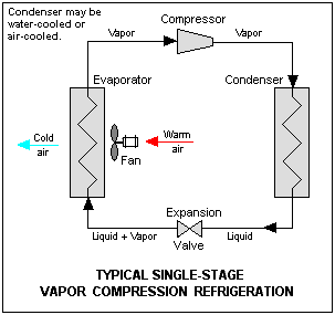
The refrigerated gas enters the compressor at low temperature low pressure and is compressed thereby leaving the compressor at high pressure and high temperature. This gas when it enters the condenser gives up the heat to the medium flowing through the condenser i.e. water/air and condenses and this condensed liquid still at a high temperature high pressure, when it flows through the thermostatic expansion valve its pressure and temperature reduces. When it enters the evaporator it absorbs the heat from the medium flowing through/over it i.e. water/air and evaporates, and in the process provides the refrigerating effect. A combination of all these major components alongwith other ancillary equipments comprises the refrigeration plant.
EQUIPMENTS
a. Compressor
The compressor being utilised in our application is of reciprocating type. Generally the compressors are available in three types of construction:
i) Sealed (ii) Semi-sealed type (iii) Open type
Sealed Type
The sealed types of compressors are generally available upto 5TR and they are hermetically sealed. The compressor and compressor drive is enclosed in the same casing.
Semi-sealed type
These type of compressors are available in capacity of 5TR and above. They are similar to the sealed type compressors having he compressor and its drive in the same housing except and this housing is in bolted construction.
Open type
These type of compressors have to be driven by a motor which is either directly coupled or V-belt connected to the compressor. The compressor and its drive are two separate units.
b. Condenser
This is generally provided in two types of design. When the medium to which the heat is rejected by the refrigerant is water, the condensers are of water cooled type design and when the medium is air, the same are of air cooled design. Water cooled type condensers are in shell and tube construction where the water flows through the tubes and the refrigerant flows through the shell. The air cooled condensers are a assembly of finned tubes through which the refrigerant flows and rejects the heat to the air which is flowing over the tubes.
c. Evaporator
When the medium which is to be cooled is air the type of evaporator used is called a direct expansion cooling coil which is in finned tube construction. The refrigerant flows through the tubes and the air flows over the tubes. When the water is the medium which is to be chilled, the evaporator is called the direct expansion chiller. This is in shell & tube construction in which the refrigerant flows through the tubes and the water flows through the shell.
d. Cooling Coil
The cooling coils in air conditioning applications are of direct expansion type or of chilled water type. These are of finned tube construction in which the chilled water or the refrigerant gas flows through the tubes and the air is drawn over the surface of the tubes. The fins are provided for increasing the effective heat transfer area. When the refrigerant is flowing through the tubes the cooling coil is turned as the direct expansion cooling coil. When chilled water flows through the tubes of cooling coil is called the chilled water cooling coil. These cooling coils are mounted along with the filters, dampers and the air handling blowers in the assembly called the air handling unit.
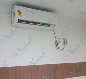
e. Air Handling Unit
These air handling units are in cabinet type sectionalised construction used in air conditioning applications and comprises the direct expansion/chilled water cooling coil, blower along with its drive accessories, face & bypass dampers and GI wire mesh filters. The air handling unit is interconnected with the other equipments in the refrigeration circuit by the cooling coil.
Along with these above mentioned equipments, there are other auxiliary equipments such as cooling tower, pump sets, piping, ducting, electrical and insulation work which are necessary to complete the installation and commissioning of the plant. The refrigeration plant comprises the high side and the low side equipments.
The high side equipmentscomprises the compressor & the condenser and upto expansion valve which is subjected to the high pressure of the refrigerant gas/liquid. The low side equipmentscomprises expansion valve, and the air handling unit/direct expansion chiller.
The installation unit for air conditioning/refrigeration system falls into two categories:-
i. Packaged units.
ii. Central plants.
Packaged Units.
Packaged type air conditioning units are factory assembled housing. The high side and low side equipments in single cabinet and they are manufactured by in various capacities as per manufacturer’s standard. These packaged units have the advantage of occupying lesser floor space, easier maintenance and faster installation. They are used in applications where conditions in the region of 25°C DBT and 55% RH need to be maintained.
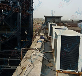
Central Plants
These comprise of the assembly of the high side and the low side equipments on site itself. For the installation of a central plant, we need two separate areas if the purpose is for air conditioning. One area is for installing the condensing unit or the chilling unit and the other is for the air handling unit.
The terminology of condensing/chilling unit is described as under:-
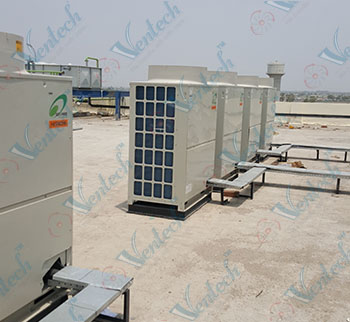
Condensing unit
The condensing unit comprises the compressor, compressor motor, shell & tube water cooled type condenser, interconnected refrigerant piping, and line accessories mounted on a common MS structural frame work. The condensing unit is connected to the direct expansion cooling coil in the air handling unit. These air generally provided for air conditioning applications.
Chilling unit
The chilling unit comprises the compressor, compressor motor, shell & tube water cooled type condenser, and the direct expansion chiller, interconnected refrigerant piping and line accessories mounted on a common MS structural frame work. The water which is chilled in the chiller is either taken for circulating through any process or it is circulated through the cooling coil in the air handling unit used for air conditioning applications. The cooling coil through which the chilled water flows is turned as chilled water cooling coil.
In the case of a central plant with a condensing unit, it is essential that the two areas are adjacent to each other and preferably also adjacent to the area which is being air conditioned whereas with a chilling unit it is not necessary to have the air handling units located in an area adjacent to the chilling unit. In any case for installation of a central plant we need the “plant room” and an air handling unit room.
APPLICATION
1. Air Conditioning
The term of air conditioning applies to simultaneously maintaining of temperature, relative humidity and cleanliness level in the area to be air conditioned. In order to achieve these, it is firstly essential to have an understanding of the external/internal loads so that the heat load calculations and be done and the plant capacity decided upon. A list of information to ascertain the load requirement is being listed under:-
- 1. Details of the areas to be air conditioned as regards its plan, elevation, orientation, beam depth, glass areas and location.
- 2. Occupancy.
- 3. Desired inside conditions of dry bulb temperature and relative humidity to be maintained.
- 4. Outside ambient conditions.
- 5. Lighting load.
- 6. Equipment heat dissipation inside the areas.
- 7. Whether the area adjacent to the department/area to be air conditioned is already air conditioned or non-air-conditioned.
- 8. Hours of operation of the plant.
- 9. No. of fresh air changes if specified.
Based on the above information, the heat load calculations are done. The heat load calculation involves the calculation of the sensible heat gain, latent heat gains, the outdoor air heat, the required air quantity and the total plant capacity required to offset the loads. The calculations done, forms the basis of the equipment selection and design and if there is any error in the heat load calculations, the same is reflected in the plant which is installed. As a thumb rule, it can be estimated that leaving aside the equipment load capacity of the plant required for any area would be 150-200 sq.ft per TR and an air handling capacity of 400 cfm per TR. But it may be pointed out that the load calculations must be done prior to making any commitment as regard the plant capacity which is required.
It may also be kept in mind that except for few special applications, in almost all the air conditioning installations the air supplied is re-circulated and therefore a path for taking back this return air is also to be defined while we design or look into the proposal for an air conditioning plant. The heat gained by this return air also forms a part of the plant load and is to be calculated separately.
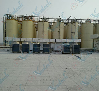
2. Process Chilled Water
For various industrial applications, chilled water is required to be circulated through the process for the extraction of heat and therefore it is necessary to install a chilling unit in order to meet the duty requirement. For enabling to calculate the load for such process requirements the following data is required in order to calculate a suitable capacity plant:-
- 1. The flow rate of water required to be circulated through the process.
- 2. The temperature of chilled water required at the inlet of the process.
- 3. The temperature of water leaving the process.
Based on these above data, the plant capacities is ascertained as under:-
Capacity (TR) = Flow Rate (USGPM) x Δt (oF) x 50012000
Where Δt = Difference in temperature of water leaving and entering the process.
SELECTING THE EQUIPMENT
Having arrived at the plant capacity to be offered, the next step is to select the various equipments. All the major equipments along with their ancillaries have to be matched to each other as regards the capacity and the operating parameters to arrive at the most economical workable selection. There are several criteria which are to be considered while selecting the equipments. Some of the major considerations are listed as under:
a. Compressor
The operating parameters of the compressors are suction and discharge temperature, and its operating speed. Keeping the discharge temperature and the speed constant, lower is the suction temperature, lower is the capacity. With the suction temperature and the speed constant, the capacity is inversely proportional to the condensing temperature. With the suction and the discharge temperature constant, the capacity varies directly with the speed. The minimum suction temperature at which the compressor is selected is 0.56°C and the maximum depends on the rating of the manufacturer which is normally 5°C. in any case we do not selecting the suction temperature beyond 4.4°C. The condensing temperature is selected between 40.4°C and 41.7°C. These parameters for the selection have been derived considering the economics and lesser operational problems.
b. The condenser size is related to the condensing temperature, the water entering temperature and the flow rate. Higher the condensing temperature, smaller is the size of the condenser and vice versa, the other parameters remaining constant.
c. Evaporator
The sizing of the evaporator is directly proportional to the suction temperature with the balance parameters of the required air/water temperature entering and leaving conditions constant. With these above considerations, the major components of the plant are selected. While it is not feasible to describe the selection criteria for all the components, it is however to be noted that they are also equally important when designing the plant.
Having selected the equipments the same are procured and then installed. Once having installed the equipments, and the commissioned the plant it is essential that a record of the various data such as pressure and temperature readings be maintained. These are compiled in a log book. It is essential that the readings are noted down correctly as it will help us in diagnosing the problems and the causes of break-down. Further, it will also point out whether any preventive maintenance is required to be carried out before the break-down actually occurs.
TROUBLE SHOOTING
There are several problems which are encountered and it is essential that the cause of the trouble should be determined as accurately as possible. Some of the problems, their possible causes and remedies are being listed.
| PROBLEM | POSSIBLE CAUSES | REMEDY |
|---|---|---|
| COMPRESSOR MOTOR WILL NOT RUN | a. Motor line open b. Fuse blown c. Starter holding coil burnt out or not getting power or correct voltage. d. Motor winding open. |
a. Close switch. b. Investigate for possible overloading. Check electrical circuits. Replace fuses when cause of failure has been located & corrected. c. Replace coil if necessary. Check for correct voltage. d. Use ohmmeter & check for open windings. Disconnect motor wiring at terminals. Instruments will indicate an infinite resistance if motor winding open. Repeat this test with all combinations. If any motor windings are open starter must be rewound. |
| UNIT SHORT CYCLES | a. Control differential set too closely. b. Discharge valve leaking. c. Motor overload cutting out. d. Shortage of refrigerant. e. Insufficient water circulation through the condenser. |
a. Widen differential. b. Check valve plate and discharge reeds. c. Check for high head pressure. d. Check for leaks, repair and add charge. e. Chock and take remedial action. |
| UNIT OPERATES LONG FOR CONTINUOUSLY | a. Shortage of refrigerant. b. Air in system. c. Thermostat setting disturbed. d. Leaking suction and/or discharge valve. |
1. Refer to 2(d) above. 2. Purge system. 3. Reset or replacing the thermostat. 4. Service valves. |
| UNIT VERY NOISY | a. Components not receiving adequate b. Loose or damaged components causing excessive vibration. |
a. Service components at proper intervals to ensure smoothoperation. b. Tighten all screws, bolts etc. at frequent intervals. Replace any worn/damaged parts immediately check mounts for obstruction, remove obstruction and adjust to ensure free floating action. Dismantle compressor and replace worn out part. |
| COMPRESSOR LOOSE OIL | a. Lack of refrigerant. b. Piston rings worn-out |
a. Check for leaks, repair and add refrigerant. b. Overhaul compressor. |
| HIGH DISCHARGE PRESSURE | a. Condenser water flow insufficient and/or temperature too high. b. Fouled condenser tubes. c. Non-condensibles in system. d. System overcharged with refrigerant. e. Discharge shutoff valve partially closed. |
a. Readjust water shutoff valve. Investigate ways of improving water supply. b. Descale the condenser tubes. c. Purge the non-condensable. d. Remove excess refrigerant. e. Open valve. |
| LOW DISCHARGE PRESSURE | a. Suction shutoff valve partially closed. b. System low on refrigerant. c. Worn out piston rings/discharge valve reed. |
a. Open Valve b. Check for leaks, repair and add charge. c. Overall compressor. |
| LOW SUCTION PRESSURE | a. Short of refrigerant. b. Clogged suction line or strainers. c. Low condensing temperature. d. Disturbed expansion valve setting. |
a. Check for leaks & top. b. Clean strainers/lines. c. Increase condensing temperature by reducing water. d. Check and readjust the expansion valve supper heat. |
| HIGH SUCTION PRESSURE | a. Excessive load. b. Worn piston rings. c. Damaged discharge valve reeds. |
a. Reduce load. b. Overhaul compressor. c. Replace valve reed. |